What if a pressure sensor has the right measurement range but still gives unreliable readings under real operating conditions? For a pressure sensor for hydraulic systems, range is only one part of the decision. Factory managers also need to account for pressure spikes, vibration, fluid connections and how the signal will integrate with equipment controls.
These considerations matter in Malaysian oil and gas operations and palm oil mills, where dependable instrumentation supports equipment performance and operational continuity. Choosing by technology name alone can leave important requirements unanswered. Assessing the duty, installation and control interface consistently makes it easier to compare options and identify the specifications that matter.
This guide compares common sensing technologies and explains how to assess operating range, pressure transients, environmental conditions, connections and electrical outputs. It also outlines the application details to gather before specifying an instrument. Totalmas supplies pressure transmitters and industrial instrumentation for Malaysian industry. The practical framework below can help you prepare for a more informed selection and find further insights on industrial solutions in Malaysia.
Key Takeaways
- Specify a pressure sensor for hydraulic systems by matching its measurement range and installation requirements to the actual duty.
- Separate normal operating pressure from pressure excursions, and check how the datasheet defines proof and burst ratings.
- Compare strain-gauge and thick- or thin-film approaches by reviewing their sensing methods and the relevant datasheet details.
- Gather circuit, existing instrument and control-system information before selecting the sensor’s connection and electrical output.
- Use a consistent checklist to align the instrument with the application and reduce uncertainty during specification.
Why Pressure Sensors Matter in Hydraulic Systems
A hydraulic pressure sensor measures fluid pressure in a system and converts that measurement into an electrical signal for monitoring or control. Pressure is the physical variable; the electrical signal carries the information to a display, controller or other connected equipment. Keeping these functions distinct helps clarify what the instrument measures and how the reading is used.
A pressure sensor for hydraulic systems lets operators observe circuit conditions rather than rely only on machine behaviour or manual checks. The reading can inform decisions about equipment operation, control adjustments or investigation of a change in system condition. It does not, by itself, guarantee a particular performance result. Its value depends on selecting and installing an instrument suited to the duty, then interpreting its signal in the context of the wider system.
Where pressure measurement fits in a hydraulic circuit
A hydraulic pump moves fluid through the circuit, while resistance from a load or restriction contributes to pressure. Actuators, such as hydraulic cylinders or motors, use pressurised fluid to produce movement or torque. Control equipment manages system operation, and pressure information may be used to monitor conditions or inform a control response. The Hydraulic system overview provides useful background on how these components work together.
The measurement point and its purpose depend on the circuit. A reading may help an operator understand a machine cycle, compare conditions over time or investigate an unexpected change. Identify the measurement location and intended use from the circuit design and control objective, rather than assuming one position or function suits every installation.
What can make hydraulic measurement demanding?
Hydraulic duty can involve changing pressure as pumps start, loads move or control valves change flow. Short pressure spikes may occur alongside normal operating pressure, so a steady-state reading alone may not describe the full duty. Vibration and mechanical shock can also affect the instrument and its mounting. The fluid connection must suit the installation and remain appropriate for the process conditions.
These considerations apply across Malaysian industrial settings. Oil and gas facilities, including offshore operations in Sabah and Sarawak, may use hydraulic equipment in demanding operating environments. In palm oil mills, hydraulic machinery may be part of equipment handling or processing operations, where plant conditions and maintenance requirements shape instrumentation decisions. These are application contexts, not assumptions about a particular circuit.
Before selecting an instrument, document how pressure changes during normal operation and identify potential excursions, vibration, shock and connection constraints. This operating picture gives the specification a practical foundation and helps align the measurement with its intended monitoring or control task.
Which Specifications Should You Compare for a Hydraulic Pressure Sensor?
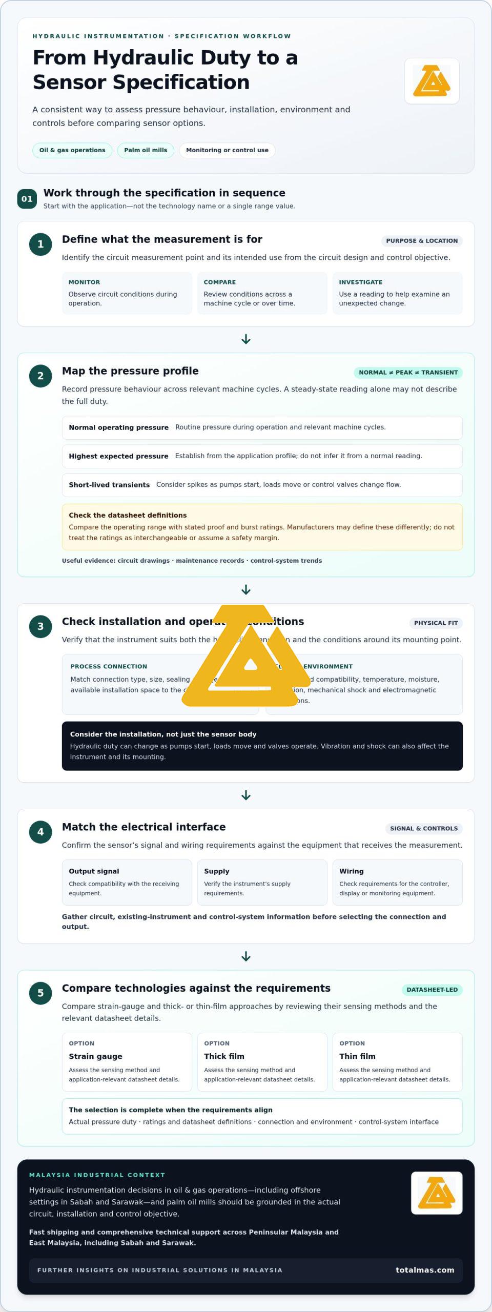
Build the comparison from the application outward. Start with pressure behaviour, then check the physical installation, surrounding conditions and receiving equipment. This keeps a shortlist from being driven by one headline value while other requirements remain unresolved. For a pressure sensor for hydraulic systems, record what the instrument must measure and how its signal will be used.
- Operating range: Record the normal pressure range during relevant machine cycles, not only a nominal system value.
- Pressure excursions: Identify known peaks and transient events from circuit documentation, operating records or control-system data.
- Pressure ratings: Compare the operating range with the stated proof and burst ratings. Manufacturers may define these terms differently, so check the applicable datasheet instead of assuming the ratings are interchangeable.
- Process connection: Match the connection type, size, sealing arrangement and available installation space to the hydraulic circuit.
- Environment and fluid: Review fluid compatibility and relevant temperature, moisture, vibration, shock and electromagnetic conditions.
- Electrical output: Confirm the output signal, supply and wiring requirements against the controller, display or monitoring equipment receiving the measurement.
Operating pressure, pressure spikes, and measurement range
Separate three operating conditions before comparing ranges: normal pressure during routine operation, the highest expected pressure and short-lived transients. Circuit drawings and maintenance records can help establish this profile. Control-system trends may also show variations across a machine cycle. Do not infer peak conditions from a normal reading alone. Compare the documented pressure profile with the instrument’s stated range and ratings, and check the datasheet definitions rather than applying an assumed safety margin.
Range selection also depends on how the reading will be used. An instrument for routine monitoring may have different requirements from one whose reading informs control decisions. In oil and gas or palm oil plant environments, document the actual hydraulic duty instead of using the industry label as a substitute for circuit information.
Connections, environment, and electrical interface
Check the connection against the equipment drawing and installation constraints. Thread form, sealing method, port dimensions and orientation affect whether an instrument can be fitted correctly. Then review the fluid and surroundings, including temperature at the measurement point, moisture exposure, vibration, mechanical shock and electrical interference. Compare these conditions with the relevant limits and compatibility statements in the instrument documentation.
Electrical fit matters just as much. Establish what the connected controller or display accepts, including signal type, supply requirements and wiring arrangement. A sensor that meets the pressure requirement may still be unsuitable if its output does not match the receiving equipment. Review the complete interface before narrowing the shortlist.
Use the checklist to compare candidates consistently, and retain the circuit details that support the specification. For Malaysian industrial instrumentation requirements, Totalmas supplies pressure transmitters and industrial instrumentation.
How Do Hydraulic Pressure Sensor Technologies Compare?
Technology names describe how pressure is sensed, not whether an instrument suits a particular hydraulic circuit. Compare the sensing approach alongside the instrument’s pressure ratings, construction, connection and electrical output. For a pressure sensor for hydraulic systems, the practical choice depends on documented operating conditions and the interface requirements of the equipment receiving the signal, not on a universal winner.
Strain-gauge and film-based sensing approaches
Strain-gauge sensing relies on deformation: pressure causes a sensing element to strain, changing its electrical resistance. Thick- and thin-film approaches use resistive elements formed as film within the sensing construction. These are high-level descriptions, and designs and characteristics vary. Check the specific instrument documentation for its construction, operating limits and stated performance rather than assuming all sensors using the same approach behave alike.
| Approach | Sensing principle | Application questions | Verify in the datasheet |
|---|---|---|---|
| Strain gauge | Pressure-induced deformation changes the resistance of a strain-sensitive element. | Does the stated range and rating suit the documented pressure duty and expected excursions? | Operating limits, pressure ratings, accuracy information, connection and environmental limits. |
| Thick film | Uses resistive elements formed as a relatively thick film in the sensing construction. | Does the documented construction suit the application and installation conditions? | Technology-specific characteristics, limits, fluid compatibility and connection details. |
| Thin film | Uses resistive elements formed as a relatively thin film in the sensing construction. | Do the instrument’s stated characteristics align with the measurement task? | Technology-specific characteristics, ratings, environmental limits and output details. |
This is a comparison framework, not a ranking. Use product documentation to compare exact limits and characteristics. Confirm that the cited ratings and compatibility details apply to the complete instrument and its intended installation.
Sensor output and control-system compatibility
Sensing technology is only one part of the selection. The instrument’s output must match the receiving display, monitoring equipment or control system. In a PLC-based installation, for example, the PLC input requirements must align with the sensor’s documented output and electrical requirements. Do not assume every sensor connects directly to a PLC or that devices are compatible because they use similar sensing principles.
Keep three decisions distinct: how pressure is sensed, how the instrument is packaged and connected, and how its signal is received and used. Review the instrument documentation alongside the control-system information so the specification addresses all three. For a separate temperature-focused application, the high-temperature pressure transmitter guide covers considerations beyond this hydraulic technology comparison.
How to Specify a Pressure Sensor for Your Hydraulic Application
A clear application specification helps engineering, maintenance and procurement teams compare suitable instruments without relying on assumptions. For a pressure sensor for hydraulic systems, document the measurement task and system interface before reviewing options. Keep confirmed site information separate from details that still need engineering review.
Build an application specification before comparing instruments
Gather information from circuit drawings, existing instrument records, operating data and control-system documentation. In Malaysian oil and gas facilities, palm oil mills and other plants, this record helps teams coordinate requirements across operations, maintenance and procurement.
- Define the measurement task. Identify the equipment, circuit and control or monitoring point the pressure reading must support. State what decision or indication depends on the measurement.
- Document pressure duty. Record normal operating conditions, known peaks and transient events from available system information. Note unresolved pressure data for engineering review rather than estimating values.
- Describe the process conditions. Record the hydraulic fluid and relevant operating conditions that affect instrument compatibility. Use actual fluid and site information, not a general assumption based on the industry.
- Capture installation details. Use drawings or existing instrument records to identify the process connection, available space, mounting arrangement and wiring route. Note vibration, mechanical shock, moisture and temperature conditions where they apply.
- Specify the signal interface. Record the connected display, controller or other monitoring equipment, including its input and supply requirements. Include the required output information from the control-system documentation.
- Mark open items. Label each requirement as confirmed, unavailable or requiring engineering review. This prevents a missing connection detail, pressure event or interface requirement from becoming an assumed specification.
Review the complete measurement and equipment context
Once the application record is assembled, compare it with the instrument documentation. Check that the stated operating limits, pressure ratings, fluid compatibility, connection details, environmental conditions and electrical output address the recorded requirements. Resolve gaps using the relevant equipment and engineering records before finalising a selection.
Consider the hydraulic circuit within the plant’s wider fluid-handling system, but keep distinct equipment duties clear. Hydraulic pumps supply fluid to hydraulic circuits; centrifugal pumps serve other process duties and should not be treated as equivalent just because both are pumps. If a project also involves pump procurement, the API 610 centrifugal pump guide covers that separate equipment context.
A well-prepared specification gives the instrumentation review a traceable basis and helps teams discuss the same requirements across project stages. Totalmas supplies industrial instrumentation for Malaysian projects.
Pressure Sensor Support for Malaysian Industrial Projects
A clear project handover helps engineering, maintenance and procurement teams keep instrumentation decisions connected to plant requirements. For hydraulic applications, share the intended measurement task and relevant system information so the review stays focused on the documented duty and control interface. This is useful when project stakeholders coordinate across oil and gas facilities, palm oil mills and other industrial sites.
Coordinating pressure instrumentation with plant requirements
Before discussing an instrumentation requirement with Totalmas, assemble a concise handover pack. Include:
- Relevant circuit drawings, equipment details and the measurement point’s purpose.
- Existing instrument records or datasheets, where available.
- Operating information describing normal conditions and known pressure events.
- Fluid, mounting and installation details that affect the application.
- Control-system or display input requirements and any known electrical interface details.
- Open questions clearly identified for engineering review.
This information gives project teams a shared reference and helps distinguish confirmed requirements from items still requiring review. It also supports an organised discussion of instrumentation in plant settings where operating equipment and control requirements must be considered together.
Supporting projects across Malaysia
Totalmas is based in Kuala Lumpur and has a product service centre in Kemaman, Terengganu. These locations provide Malaysian industrial project teams with local points of reference when coordinating instrumentation requirements across sites. For projects involving Peninsular Malaysia and East Malaysia, including Sabah and Sarawak, clear documentation helps maintain continuity as requirements are communicated between stakeholders.
Bring your application details and project questions together for a focused discussion about the instrumentation requirements.
Discuss your industrial instrumentation requirements with Totalmas.
Make the Next Instrumentation Decision with Confidence
Turn the instrument selection into a practical project record. Capture the measurement purpose, supporting equipment details and outstanding engineering questions so everyone involved can understand the basis for the decision.
Before procurement proceeds, align that record with the site’s installation and control documentation. A considered handover helps teams carry the selected requirements into planning and implementation without relying on assumptions.
Share your industrial instrumentation requirements with Totalmas to define the next steps for your project specification.
Frequently Asked Questions
What is a pressure sensor used for in a hydraulic system?
It provides pressure information that operators or control equipment can use to observe a hydraulic circuit. For example, a plant team may review readings at different stages of a machine cycle to investigate a change in operation or compare conditions over time. The sensor is one part of the measurement arrangement; how its reading is used depends on the equipment, control strategy and monitoring purpose defined for that installation.
How do I choose the pressure range for a hydraulic pressure sensor?
Choose a range using documented pressure conditions across the operating cycle, including known peaks and short-lived events. For example, a maintenance team can compare circuit records with readings taken during different operating states rather than relying on a single normal reading. Then review the instrument documentation for its operating range and pressure-rating definitions. Do not substitute an assumed margin for missing site information; record unresolved values for engineering review.
Are pressure sensors and pressure transducers the same thing?
The terms are often used interchangeably in industrial instrumentation, but terminology can vary between manufacturers and documents. A datasheet may use “sensor” for the pressure-measuring device and “transducer” to emphasize conversion into an electrical output. Do not rely on the label alone when replacing an existing instrument. Compare the documented measurement range, electrical output, connection and interface requirements to establish whether a candidate fits the same application.
What causes pressure sensor failure in hydraulic systems?
Failure can result from conditions that exceed the instrument’s stated limits or from installation problems. Potential contributors include pressure events, repeated cycling, vibration, mechanical shock, unsuitable fluid compatibility, moisture exposure or damaged wiring. A fault can also originate elsewhere in the measurement loop, such as at the connection or receiving equipment. Review operating records, installation condition and electrical connections together before concluding that the sensor itself has failed.
Can a hydraulic pressure sensor connect to a PLC?
Yes, if the sensor’s electrical output and supply requirements match the PLC input and wiring arrangement. Before connecting it, compare the sensor documentation with the PLC or input-module documentation, including signal type and configuration. Also confirm how the reading will be scaled and used in the control logic. Compatibility with one PLC setup does not establish compatibility with another system or input module.
Which pressure-sensing technology is best for hydraulic applications?
There is no universal best choice. Strain-gauge and thick- or thin-film designs use different sensing constructions, but the technology name alone does not establish suitability. Compare the manufacturer’s documented operating characteristics with the hydraulic duty, installation conditions and control interface. For example, a replacement in a palm oil mill should be assessed against that circuit’s records and system requirements, not selected solely because the existing unit is described as a particular technology.